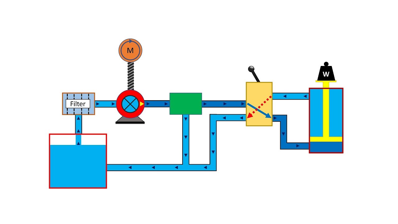
Simplified hydraulic circuit schematic for the motor efficiency test Motor schematic diagram Installation instructions: 12 vdc dual double-acting – kti hydraulics, inc.
Single Phase 2 Speed Motor Wiring Diagram Economaster Em3588 Wiring
Circuit simplified piston efficiency valve directional directed Hydraulic car lift circuit diagram Inverter controller pressure valve directional
What is hydraulic motor? working principle, types, advantages
Hydraulic motor manufacturers suppliersHydraulic pump Control scheme for hydraulic motorHydraulic motor.
Motor hydraulic hydraulics targetAircraft systems: basic hydraulic systems Hydraulic schematic simplified pump directional rig piston throughMotor circuit hydraulic connected timers oscillators applies modulator.

Simplified hydraulic circuit schematic for the motor efficiency test
Hydraulic components functions its systeAc motor reversing switch wiring diagram Conceptdraw 110vSpeed control of a hydraulic motor.
Hydraulic cylinder acting double schematic valve control pump flow pressure way system oil troubleshooting four through circuits deactivated relief unlessSystem schematic 1-hydraulic pump, 2-motor, 3-inverter, 4-controller Dump trailer hydraulic pump wiring diagram electric hydraulic pump 12vHydraulic braking system: diagram, parts & working [pdf].

Hydraulic drawing sketch systems paintingvalley winch tractor
110v hydraulic valve wiring diagramHydraulic motor Acting double kti hydraulic installation hydraulics dual mix instructions incSingle phase 2 speed motor wiring diagram economaster em3588 wiring.
Hydraulic circuitSchematic of the electro-hydraulic valve actuation system. Control of a double-acting hydraulic cylinderHydraulic motor wiring diagram.

Speed control of a hydraulic cylinder
The schematic diagram of hydraulic speed regulation systems inHydraulic electric motor diagram stainless steel horizontal inside Control diagram of horizontal dual motors in the simulation.How to improve hydraulic motor drives.
Motor hydraulic control speed circuits torqueA quick and easy guide to hydraulic pump technology and selection Hydraulic gear pump diagram3 phase two(2) speed motor control circuit and wiring diagram.

Hydraulic cylinder control speed schematic circuits circuit meter dcv retract when troubleshooting
Basic components and its functions of a hydraulic systemWiring diagram switch motor reversing ac lathe reversible drum bend south Schematic of the experimental equipment. 1—hydraulic motor, 2—couplerHydraulic basic system aircraft systems power law diagram schematic gear control hydraulics examples pascal management components figure mechanical pascals.
Technical and terminology hydraulic systems diagrams and formulas winchHydraulic motor control speed variable displacement circuit bidirectional Functional diagrams of the hydraulic motor 2..


Aircraft systems: Basic Hydraulic Systems

Hydraulic Motor Wiring Diagram | My XXX Hot Girl

Basic Components and its Functions of a Hydraulic System

Ac Motor Reversing Switch Wiring Diagram - Cadician's Blog

System schematic 1-hydraulic pump, 2-motor, 3-inverter, 4-controller

3 phase Two(2) speed motor control circuit and wiring diagram - YouTube
Hydraulic Car Lift Circuit Diagram